System in Motion
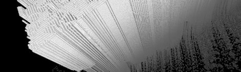
Growing vs Building. The idea of growing inhabitats instead of building them still belongs to sorcerer’s apprentices but computing can give us glimpses. This is a visualization of previous cell[f] assembly […]
Growing vs Building. The idea of growing inhabitats instead of building them still belongs to sorcerer’s apprentices but computing can give us glimpses. This is a visualization of previous cell[f] assembly […]

Inspired by the reading of AN EVOLUTIONARY ARCHITECTURE by John Frazer and the generative toolbox. Structure generations based on John Orton Conway’s Game of Life. The goal is to explore the […]
A [near] perfect mathematic structure affected by a chaotic process The variety of forms in nature seems endless. Patterns can derive from mathematical rules. Habitats can derive from patterns. The […]

Fossile-like structures made of flat quad panels. Panels can be assembled along their folded sides. The script works with free from surfaces (trimmed or not_see conditional minimum distance between any […]

Script developed to populate free-form surfaces with overlapping irregular panels otherwise known as ‘shingles’. Sculpture project for North Scotland by biomorphis. Call Main() Sub Main() Dim strSurface : strSurface = […]
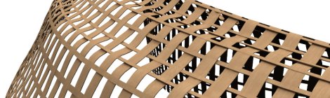
The house is a retreat for an artist in the Scottish Highlands (visit full project on www.biomorphis.com) The initial roof structure concept was to express the multi-layering of the roof-build-up […]

during the course of my investigation of simplistic model ideas with large number of different outcomes, I found myself working on a circular stack of triangles which are defined by […]
TAC – Technically Advanced Construction 2011 Milano Organized by Politecnico di Milano and friends from Co-de-iT . One of the most interesting events for 2011 in Italy on advanced construction, […]
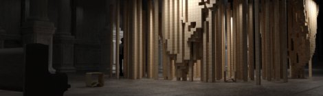
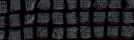
Gfield script is an attempt to visualize the units of space-time as they are distorted by a gravity type field. given that each ‘cube’ represents a unit of space-time, greatly […]

Option Explicit ‘Script written by <pierre forissier> for nCodon Call Main() Sub Main() ‘>>>>>>>>>>>>>>>>>>>>>>>>>>>>>>>>> ‘Points cloud for twirl base curve Dim arrPoint0, arrPoint1, arrPoint2, arrPoint3 Dim arrCtlPts() Dim i Dim […]

/‘concrete geometries’ – a resultants of a continual actualization of the moment now/ It is suggested that a change/time is a fundamental element of a form and that it is […]
Unspecified Form by Bojana Vuksanović an infinite number of possible forms Overview 1. Introduction 2. The cultural background 3. The perfect form 4. Mathematics of space, objects and relationships 5. […]

Exploring T-Splines options and manual operations.

Pavilion modelled with T-Splines trial version for rhino. It’s a really nice plug-in….

00014 00014 test rhino/v-ray rendering engine based on ‘Bounding box, divide interval and box component’ definition found at ARTC MIAMI / ARTC Miami / (requires registration/otherwise free) gh definition / […]
Planned Spontaneity by Bojana Vuksanović Overview 1. Introduction 2. Planning 3. Spontaneity 4. The Issue of Complexity 5. Planned versus Spontaneous 6. Planned Spontaneity 7. Conclusion Read the rest of […]
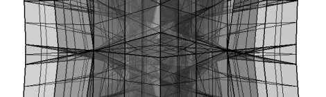
We have just received the news that Pierre Forissier’s Art Fund Pavilion, entered for Cre8Architecture Office is one of the 19 entries chosen to be exhibited at the Lightbox, together […]

Parametric pavilion modelled in rhino + grasshopper. I started the whole pavilion with 5 curbs (that will be lofted) and a grid of perpendicular lines (that will make the ribs […]
A 3d diversion (away from proper work) inspired by fascinating photos on flickr by seier+seier+seier of an agricultural building by German architect Hugo Häring from the 1920s. Modeled in rhino3d […]

Inspired by DRL TEN Pavilion. Modeled in Rhino with Paneling Tool onto loft surface. Original panel modeled in SketchUp (see below) and imported into Rhino. Seamless joints are obtained by […]
